Showing posts with label technical. Show all posts

01 June, 2010

Vapour Lock

Owners of the 1999 and 2000 model of the Suzuki Hayabusa may face this problem when they were to increase the engine compression (in one way or another); resulting in higher ambient temperature under the fuel tank. Add to that equation a in line fuel filter, it's a very good recipe for vapour locking the fuel system.

According to wikipedia,

Vapor lock (also known as vapour lock) is a problem that mostly affects gasoline-fueled internal combustion engines. It occurs when the liquid fuel changes state from liquid to gas while still in the fuel delivery system. This disrupts the operation of the fuel pump, causing loss of feed pressure to the carburetor or fuel injection system, resulting in transient loss of power or complete stalling. Restarting the engine from this state may be difficult. The fuel can vaporise due to being heated by the engine, by the local climate or due to a lower boiling point at high altitude.

The 99-00 model of the Suzuki Hayabusa utilises the external fuel pump as opposed to the in-tank fuel pump from 01 model onwards. This provides the opportunity for vapor lock to occur. The external fuel pump runs 2 fuel lines, 1 inlet and 1 return line. The inlet is gravity fed and is not pressurized. This allows the fuel to vapourize when the engine compartment temperature rises too much due to heat soak.

The fuel pump when moved to the interior of the tank helps prevent vapor lock, since the entire fuel delivery system is under high pressure and the fuel pump runs cooler than if it is located in the engine compartment. Under high pressure the fuel will be harder to vapourize and thus vapour lock is almost unheard of in K1 models and above.

What are the causes of vapour lock?

A vapor lock is more likely to develop when the vehicle is in traffic because the under-hood temperature tends to rise. A vapor lock can also develop when the engine is stopped while hot and the vehicle is parked for a short period. The fuel in the line near the engine does not move and can thus heat up sufficiently to form a vapor lock. The problem is more likely in hot weather or high altitude in either case.

What are some solutions if you have a vapour lock issue?

  1. Rerouting of the fuel lines away from heat generating components,
  2. installation of a fuel cooler or cool can,
  3. shielding of heat generating components near fuel lines,
  4. and insulation of fuel lines.
Amongst the above suggested solutions, you can also consider swapping to an in-tank fuel pump which requires the replacement of the entire fuel tank, fuel pump some fuel line fittings. I have personally tried items 3 and 4 with good results.

If you have a fuel problem, do check if it is caused by vapour lock. You would want to be caught stuck in traffic with a stalled engine and unable to start due to the vapour lock issue.

02 January, 2010

Exhaust Performance and Scavenging

A very clear and concise explanation of the process of exhaust gas scavenging and how it's affected by exhaust size, length and cam timing.

The Basics

As are most things automotive, the exhaust system is a compromise. It must balance noise and performance. In addition, the exhaust system can be designed to increase performance in the low RPM range or at the top end. All of these aspects must be taken into account when designing the best possible setup for a given application. A larger pipe diameter typically will reduce backpressure allowing the engine to expend less energy pushing out exaust gas. If the system was being restricted, this will result in more power at a certain range of RPMs. The downside to larger pipes is a loss of power in other areas of the power band and increased noise.

Scavenging

At first glance one might think that a maximum pipe size would result in the best performance. It should provide the most flow. This is true for a steady stream of gas. An engine ejects exhaust gas out of the ports in pulses though. This results in a stop-go-stop-go situation as the exhaust valve opens and closes. A properly sized pipe will help to suck the gases out of the cylinder at certain RPMs. Since air has mass and velocity, it has momentum. When in the scavenging RPM, the exhaust charge exiting actually creates a vaccum for part of the exhaust stroke. This provides for a nice boost in power and torque. For ideal scavenging an exhaust speed of 240-260 feet per second is desired. Thus as engine speed increases for a given displacement so must the pipe diameter.

Below is a typical graph of exhaust port pressure vs. piston position:


NOTE: The exhaust pressure during scavenging nets out to be positive. Thus there is not an all around vaccum. Energy is still being wasted pushing exhaust gas out. The scavenging is not "free". Work is still done. Scavenging merely helps to aliviate what would be even more work being done by the engine. Also note that the psi values will vary from engine to engine, but the curve remains approximately the same. Values over 6 psi are generally considered excessive backpressure.

The graph above is a typical representation of what exhaust port pressure looks like as the engine rotates through almost a full revolution during the scavenging RPMs. Exhaust pressure builds as soon as the exhaust valve opens. This occurs before bottom dead center. Most of the torque the engine generates is produced by 90 degrees, thus it is not necessary to keep the exhaust valve closed much past 90. By opening the exhaust valve early, the high cylinder pressure helps to accelerate the charge in the exhaust manifolds. Pressure peaks before bottom dead center and then rapidly falls as the accelerated charge pulls the exhaust out of the engine. As the piston approaches top dead center, the intake valve opens. Pressure drops again and the exhaust gas actually helps to suck the intake charge into the cylinders.

These ideal conditions can only be met at certain RPMs. To do this one can vary the size of their piping to chose what will provide them the best performance. Smaller pipes will move an equal volume of gas at a higher speed. This typically comes at the expense of increased backpressure (resistance to flow) which inturn leads to poorer performance. A smaller pipe will help to maintain the ideal exhaust gas velocity when the engine is running in the lower RPMs. This provides for a torque boost off the line with improved streetability and driveability. For this reason many manufacturers size their pipes on the more conservative side. As the RPMs increase though, the backpressure builds due to the excessively small pipe size. This pushes the velocity of the exhaust gas out of the scavenging range and saps power on the top end, reducing performance in that spectrum.

A larger pipe will maintain ideal exhaust gas velocity on the top end. This will increase peak power. The downside comes with a slow exhaust charge on the low end. Their will not be enough suction to aid in the expulsion of exhaust gas. Torque will suffer in the low ranges for this reason. Too large or too small of a pipe will push the scavenging bonuses out of the useable RPM range and will result in diminished overall performance. It is important to size the piping correctly for the desired application: low end or top end. One should also consider how this will effect the rest of the car. For instance, if the car has an automatic with a stall speed of 1,500 RPMs it won't do any good to have all the power on the top end when off the line performance will suffer terribly. Likewise if the car is mainly driven in the city or through heavy traffic, a lack of low end grunt might make driving more of a chore.

On valve overlap scavenging also helps to draw in the fresh intake charge. The pressure in the exhaust port drops again and the exhaust flows more easily. It should be noted though that too much exhaust velocity on overlap can cause "over scavenging". This occurs when the exhaust vaccum becomes so great, due to overly small tubing, that it actually sucks the intake charge right through. This leaves spent charge in the cylinders and causes a loss in performance.

Common Views

A couple of commonly recommended modifications are increasing backpressure for lowend performance, and the use of equal length headers. Backpressure is almost always a bad thing. The higher velocity of a smaller pipe is what one wants on the low end. Unfortunately this ultimately chokes off the top end to an extent. Since these two go hand in hand (small pipes and top end back pressure), people often consider them the same. They are not. Putting a sharp bend in a pipe will cause high backpressure, but it will have little benefit for performance and scavenging. Backpressure is very useful for quieting an exhaust though and muffling the sound waves. As for equal length headers, companies often claim that they help with scavenging. They are used to line the exhaust pulses up. This can help during scavenging as the exiting charges will not try to occupy the same collector at the same time. Instead, the exhaust pulses will alternate and "zipper" there way into the collector. This results in smooth flow and optimal performance. Equal length headers, or headers designed to take advantage of scavenging in general are a plus. It is important to buy from a reputable company though as equal lengths will not guarentee optimal performance. Dynometer testing is the best way. Most reputable exhaust companies do make use of a dyno which gives some assurance as to what one is getting.

Summation

1. Choose a smaller pipe for better low RPM performance, a larger one for high RPM performance.

2. Remeber that peaks are not everything, as seen in Understanding Performance, thus a proper sized pipe will deliver better results than one that may give the highest peak low end or top end performance.

3. Back pressure is almost always a bad thing.

Article from: http://autolounge.net/tech/exhaust.html

09 September, 2009

CBR 600RR ABS

Honda testing ABS brakes on CBR600RR


by Jeremy Korzeniewski on Jun 14th 2008 at 11:39AM


Many motorcycles in today's market feature anti-lock brakes, including models from Honda like the Interceptor and Silverwing scooters. Now, though, the red-winged manufacturer of motorcycles has announced a new system which completely removes the rider's direct connection with the front and rear brakes. Instead of a cable connection, the system uses brake-by-wire technology and allows an on-board computer to apply pressure to both the front and rear brakes as it sees fit. This new system is expected to debut on sportbikes first, which raises some eyebrows in the cycle-riding community. The highest performing bikes have ridiculously powerful brakes which are capable of locking up the front tire very easily. Still, hardcore riders have proven very reluctant to give up any control to computers, especially on race tracks, where supersport bikes are expected to thrive. Being Honda, though, there is a prevailing sense that the technology will work. Expect the new combined ABS system to proliferate to all of Honda's two-wheelers in the near future.

[Source: Honda]


Honda Announces World's First Electronically-Controlled 'Combined ABS' for Super Sport Bikes

Honda has announced the world's first electronically-controlled "Combined ABS" for Super Sport motorcycles, aimed at combining ABS and CBS systems into one system that applies the basic advantages of both, while specifically addressing the requirements of a Super Sport context.

In order to achieve this, the particular characteristics of Super Sport bikes, such as short wheelbase, are taken into account. The system also operates without interference to sports riding, and with an emphasis on maintaining full rider control.

The system consists of an electronically controlled combined "brake by wire" system with an innovative stroke simulator. Direct motor control ensures precise operation of the ABS. The components are divided into several smaller units so there are more, but smaller units than in previous systems.

The system's effectiveness is due to four main factors:

1. Electronic control of the CBS, allowing more advanced control of brake force. This provides a more sensitive distribution of brake force over both wheels.

2. Measurement of rider input force on each lever. The ideal brake force on both wheels is generated accordingly, providing optimum distribution and minimising vehicle body reaction.

3. An "ABS modulator" which ensures late triggering of ABS, and smooth ABS intervention.

4. Small size meaning that the system's components can be well integrated in the motorcycle's package. Thus mass-centralisation, a key feature for Super Sport bikes, is supported.

All the basic ABS and CBS functions are provided, including the prevention of wheel lock, improved balance and easy operation. This is achieved without any compromise to stability during ABS operation. Pitching is minimised so that the bike keeps its normal position. Overall, sport riding performance is uninterrupted - cornering feel remains the same and controllability is enhanced.
Have read several good reviews on the application of ABS on track going sportsbikes. Apparently as it is now, Honda has gotten the idea right and gotten it to work quite amazingly. Throw in traction control and some other high tech gadgetry... riding like Rossi will soon be easily achievable by the average rider.

30 July, 2009

Aiming the front headlight

Here's a quick guide to adjusting your Hayabusa headlight so that it doesn't glare the other road users and at the same time provide you with the proper illumination of the road.

This is extremely useful for both halogen/conventional bulb and HID users.

Step 1 (requires a friend's help):
Sit on the bike and get friend to measure the height from the ground to the center of the headlight.

Step 2:
Mark on a line on wall (using masking tape) the same height you've obtained earlier.

Step 3:
Mark another line (using masking tape) 5cm below the 1st tape line, then remove the 1st tape line.

At this point there should only be one tape on the wall.

Step 4 (low beam adjustment):
Park the bike 5m away from the wall and switch on headlight to begin adjustment.

The aim is to get the top of the beam at just below the tape line. (For HID, it can be a tad lower {~10 - 15 mm}, use your own discretion)

The center of the beam should be centered directly in front of the bike.

*adjustments to be made when bike is fully settled and loaded (with the rider, rider + pillion or luggage)

Step 5 (High beam adjustment):
Using the knobs on the headlight assembly, adjust until the bottom of the high beam is lying on the top of the tape line.
(This could be a tad higher too {~10 - 15 mm}, for riders who often travel at extremely high speeds and require illumination to a further point)

Step 6:
Re-assemble everything back and celebrate a job well done.

22 July, 2009

24volt Start System Harness With Dual Battery Auto Charge Circuit


Designed for those who need a 24 start system and don't know how to wire it up. Tiger Racing has just what you need. This custom 24 start harness has everything you need to hook up a second battery with all plug and play connectors. Both batteries will auto charge with bike is running. No switches to mess with.
If you have a big bore motor, you'll want one of these for sure.

Price: $159.95 USD

As I saw this product on sale, it actually amazes me the profit margin of such products. As mentioned in the earlier post, it's actually a rather simple circuit, and the cost of the components are not too high as well. Anyway, the same can be said for this circuit. I've already gotten the circuit diagram out for ages, just never gotten down to wire it up for my bike. I'll be staying with my manual switch for a long time to come I guess. Until the day my hand itches for some DIY project, this will be next in the list.

24 April, 2009

1100cc 2-stroke triple Superbike

Imagine the power to weight ratio of what the Superbikes are getting these days. Imagine adding 50% more to that! Imagine no more as there's a bunch of crazy enough people to build a 1100cc 2-stroke engine making more than 250hp.


One for the "Because We Can" file: What do you do when you're bored with the paltry horsepower from a garden-variety Japanese superbike? We've seen power output from the Japanese fours plateau around the 150-hp mark (at the rear wheel on a dyno) for a few years now, and the OEMs seem to be focusing more on rideability rather than the exponential increases in torque and horsepower we've grown accustomed to over the last three decades. If they can make 220 hp MotoGP bikes, they can make them for us. If they wanted to.

Stephen Rothwell of The Two Stroke Shop, located in Tropical North Queensland, Australia, decided to tackle this crisis by using tried-and-true technology: the two-stroke engine. Rothwell had heard enough of legendary two-strokes like the Yamaha TZ750, so he decided to build his own legend. Rothwell and partner Wayne Wright (who designed two-stroke motors for GP race teams in New Zealand) were already building complete top-end kits for Yamaha two-stroke motors, so they already had some of the parts and the know-how for such a project.

"What the world needed was an answer to the current literbikes, which we find anemic," Rothwell told me over the phone. "If a bike can't hoist the wheel in 4th gear off the throttle it's not a superbike." The 1100cc three-cylinder TSS1100GP should have no such problems; when completed, it should make 250 hp at the rear wheel and 160 ft.-lbs. of torque. A powervalve will keep things rideable, with a characteristic hit of power as the revs climb. The chassis will be a lightly-modded Kawasaki ZX-10R ("it's beefy enough") and Rothwell expects the wet weight to be under 340 pounds: "when you dismantle a literbike and see how heavy that four-stroke motor is, it's just sad, really." The next project? The 112-hp TSS500 engine installed in a Yamaha WR450 supermoto chassis. "There's nothing 'super' about a four-stroke supermoto," sniffed Rothwell.

Not crazy enough? Rothwell and Wright can build you a 2200cc four-cylinder that could pump out 500 bhp and 300 ft.-lbs. of torque (add 10% if you want to run alcohol), although he admits that would be "far too much for a motorcycle, even by our standards." But the goal of TSS isn't to crank out demented one-off specials for wealthy lunatics. Rather, it's to bring attention to the efficient, powerful, and even environmentally friendly (Rothwell says these engines could be Euro3 and CARB compliant with the use of direct-injection technology) potential of two-stroke motors. The hope is that the Japanese factories will return to the smokey, wheelie-ing ways of their youth (minus the smoke) and build light, fast and durable motorcycles that can scare the crap out of us.


For more information: click here

23 April, 2009

New Map Loaded

Loaded a new map into the power commander just now. Made some adjustments based on all the rides I've been doing over the months.

Lean down some of the regions for fuel economy when going touring and chugging along in stop-and-go traffic. Also tried to keep a certain level of richness in that mixture to reduce the running temperature of the engine.

Overall throttle response have improved, toned down a bit of the torque at the lower end to help the engine rev up faster through the lower ranges. Pulling harder now with the faster revs. Shall do a separate dyno run to verify the results on the 2 maps.

Dyno will be posted at a later date when I get some time to go do the runs.

14 April, 2009

Williams Helical Camshaft

Introduction

The Williams Helical Cam (WHC) is a new type of mechanical Variable Valve Actuation system (VVA). More specifically it is a camshaft which allows the valve opening duration to be varied over an extremely wide continuous, stepless, range – all the added duration being at full valve lift.

The WHC was developed in the early years of the 21st century and of all the competing types of mechanical (that is, not “camless” types - electromagnetic or hydraulic) VVA systems it would appear to be the most capable and promising. It is still little-known amongst the mainstream automotive engineering community. One of the surprising and little-known facts about VVA systems in general is that, almost without exception, they are not new ideas. Most were first heard of many years ago – some have their origins in the age of steam engines. That they are not in wide use is a reflection that they are all lacking in some aspect of variable valve actuation.


For example, probably the most widespread in use and the most successful is the Honda VTEC (and the essentially very similar systems from other companies). There is no question that VTEC is very effective – in the Honda S2000 the engine power is virtually doubled compared to a non-VTEC version of the same engine. Otherwise its capabilities are limited. Its operation is strictly a stepped process and this precludes its use in the more exotic forms of engine load control.

Current research into these forms of load control includes Early Inlet Valve Closing (EIVC), Late Inlet Valve Closing (LIVC) and Homogenous Charge Compression Ignition (HCCI). None of the existing available mechanical VVA systems can adequately allow any of these forms of load control. BMW’s Valvetronic probably comes closest to being able to perform EIVC but even here it is not wholly successful. At valve opening durations short enough to allow idle and very low load situations, the unavoidable very low valve lift (that must accompany short duration with this type of system) has a throttling effect – and that is exactly what EIVC is trying to avoid. With the Valvetronic the effect is more “throttling-by-low-valve-lift” than true EIVC. It would seem almost physically impossible to achieve sufficient valve lift at durations short enough to allow true EIVC – maybe not even with electromagnetic/hydraulic VVA arrangements. The BMW Valvetronic is an example of the “oscillating cam” class of mechanical VVA systems – there are many, many other members of this class in the files of the US Patent Office, all with the same limitations.

Details

The WHC is distinctly different from competing VVA systems in that it incorporates a new and unique mechanical principle. Genuinely new mechanical principles are almost unheard of – especially in the automotive world. The WHC very distantly belongs to the very numerous general “coaxial-shaft-combined-profile” class of cams as most recently typified by the work from Clemson University (whose cams are essentially identical in principle to many other cams in the USPTO files, first appearing as early as the 1920s, number 1527456 from 1925 being a good example). This class of coaxial cam varies the valve opening duration by moving the relative positions of two adjacent cam lobes on the one coaxial camshaft in a circumferential manner – the follower riding on the combined profile of both lobes.

The inescapable problem is that the duration range is not very wide. Not enough for power at really high RPM and certainly not enough to attempt engine load control by LIVC. The WHC importantly differs from other members of the general class by having a unique helical movement – a combined circumferential and axial movement of the two profiles. Surprisingly, because of this movement, the WHC in theory has no practical upper limit to its duration range. That is to say, the duration can be increased until the closing flank of the cam lobe reaches the opening flank – a duration of 720 degrees. In a typical application the WHC would have a continuous duration range from about average for a road-going general purpose engine (say, about 250 degrees measured at normal valve clearance) to about 100 or 150 degrees above this. That is, from 250 degrees to 350/400 degrees.


The duration range of the WHC is accomplished in what most car enthusiasts or automotive engineers would agree is the “traditional” or most desirable manner a VVA (or variable duration) system should operate. The valve is opened at normal rates of acceleration, jerk, etc, and then held open at its maximum lift for whatever duration is required before being closed at a normal rate. No matter how short or how long the duration, the opening and closing rates are always unchanged. Another surprising thing here is that this style of duration change over a very wide range has never, in the very long history of the internal combustion engine, been achieved before by a mechanical VVA system no matter how complex or expensive. The only other arrangement that can rival this for width of range is a system where the lobes on two closely-spaced separate camshafts are bridged by a pivoting lifter which operates the valve. The basic idea being that one camshaft opens the valve and the other camshaft looks after the closing of the valve. Changing the relative phase of the two camshafts has the effect of changing the opening duration of the valve. This works well enough but at long durations the lobe on one camshaft may reach full lift before the other even starts to move the follower. This has the effect of halving the full lobe lift (and rate of lift) of each camshaft, at long durations the valve lift (and rate of lift) is somewhat lacking. In most applications the valve lift needs to be at a maximum especially at long durations.

Needless to say this is another of the very old existing ideas which are at regular intervals dug up and proposed as a “new” idea. Recently it has been revived in an arrangement where the two camshafts are combined in the one coaxial shaft with a rocking follower acting on the separate cam lobes. Although more compact than the two separate camshafts layout it still has the same limitations – perhaps even more so.

Mechanism

Although in essence a quite simple idea, to describe the actual mechanism and its operation is almost beyond the power of the written word. Even when held in the hands and worked through its duration range it can be difficult to understand just what is happening and how the WHC generates its continuous range of profiles. The mechanism of the WHC is a coaxial shaft arrangement where the outer shaft carries the main body of the cam lobe. The main body of the cam lobe is in its maximum duration shape (or profile) form. Typically the main lobe body would have a duration of about 400 degrees. The lobe is very long axially, about 45mm, and its profile consists of conventional opening and closing flanks separated by about 170 degrees of constant radius over the nose of the lobe. The lobe has a helical slot machined into it that has a helix angle of about 35 degrees relative to the rotational axis of the camshaft. The width of the slot is equal to the angular extent of the closing flank of the lobe. One edge of the slot extends diagonally the full length of the lobe across the 170 degree constant nose radius. The other edge is ground so that it is all at base circle level. The slot in fact replaces the closing flank on the main body of the cam lobe. Bridging the slot is a segment of lobe (about 10mm in thickness) which is ground to the profile of the closing flank. The segment is attached to the inner shaft. One edge of the slot has a constant cylindrical radius, the same radius as the lobe’s nose radius. The other edge has the radius of the lobe’s base circle. A small region along each edge of the closing flank segment has the same constant radius as the edge of the slot that it is adjacent to. This means the segment can be positioned anywhere along the helical slot and there will always be a smooth transition for the follower to and from the segment. The lobe segment is fixed to the inner shaft so any relative axial movement has the effect of changing the valve opening duration. The follower is arranged so that it always remains aligned with the segment which remains stationary axially. As the slot has a helix angle of about 35 degrees, any axial movement of the outer shaft causes the segment to rotate, exposing more or less of the nose constant radius and thus changing the duration. Make sense? Maybe not. This somewhat tortuous and convoluted explanation disguises the fact that the WHC is actually quite a simple mechanism. This brief description is not the entire story and more details, drawings etc. are available online on the USPTO website – the patent number is 6832586. The slightly indescribable and mind-boggling way it operates probably accounts for the fact that the helical movement principle has never been suggested before let alone built and run in an engine. New mechanisms, even minor detail ones, are almost unheard of – the WHC is a distinct contrast to the literally thousands of VVA designs in the USPTO files alone.

Cam Profile

The base or shortest duration profile of the WHC system is almost identical to a standard production engine profile. The WHC base profile belongs to the general group of lobe shapes which are used with pivoting cam followers – especially those with a fairly high rocker ratio. This family of lobe profiles are characterised primarily by not having a very great actual lift directly at the lobe (usually referred to as “lobe lift”). The lobe lift is enlarged by the rocker ratio which often is around 2:1 resulting in quite high lift at the valve. As the duration etc. is as for a normal lobe this results in the nose of the lobe having a very rounded-off (or “snub-nosed”) appearance. The radius of curvature of the nose region (about the axis of rotation of the camshaft) is often very close to being a constant radius over an angular extent of about 20 degrees or so. The WHC principle requires that this 20 degree region is modified to make it a true constant radius. In some cases this requires as little as 0.25mm (or less) to be removed from the nose. The constant radius area is then blended - in to the curvature of the standard opening and closing flanks.

Generally speaking, the modified minimum duration profile is identical in appearance to the standard profile – at least to the naked eye. When measured very accurately, the rates of acceleration, jerk etc. in the nose region are slightly higher than standard but only marginally higher. The WHC expands the duration by adding to the nose constant radius area and removing an equal amount from the base circle constant radius. The 20 degree constant radius area on the lobe nose typically can have about 150 degrees added to it. The 150 degrees is the extra duration. In effect, the opening and closing flanks “open up” exposing progressively more and more constant radius on the lobe nose. As both flanks are unchanged, the rates of lift/acceleration etc. and the total lift are also unchanged – no matter how much constant radius is added to the nose.

A critical question– is this the best way of making a longer duration profile? With the WHC the question is not entirely relevant. The intention is not to use the WHC principle to obtain a “fixed” profile but to develop a minimum duration profile that best suits a cam with totally variable duration control – which is something quite different. If the profile was for a conventional non-varying cam the answer would have to be “probably not”. It would certainly make a quite useable cam but not a really good cam. Certainly in the past, some long duration cams were made exactly in this way – by “opening-up” a standard profile. Even at present many racing cams are made this fashion (or at least with a lot of constant radius on the nose) for some oval track competitions in the USA. In certain classes the valve lift has to conform to the “limited lift rule” – even some very long duration cams. This results in a very distinctive “flat” region on the peak of the lift curve graphs of the cams. These “lift rule” cams rev to high RPM as well (or better) than more conventional racing cams. Usually with a high performance cam the lift is increased, the point being to get more flow into the cylinder. High performance cams generally have greater lift and greater rates of opening and closing of the valve. The aim is to maximise the cylinder filling while keeping the duration as short as is feasible. Keeping the duration as short as possible assists in retaining the lower RPM performance. In a sense the amount of lift/rate of lift etc. can be “traded” against the valve opening duration. If, for a particular application, lower RPM performance is not very important the amount of lift etc. can be kept at moderate levels and the duration increased. That is; the lift etc. and duration are roughly inversely proportional to each other.

This is the situation to some extent with engines driving water or air propellers, the engine more-or-less running at constant speed. With wheeled vehicles, no matter what the application, generally there is some need to restrain the amount of duration to retain at least some lower RPM performance. Even in racing, most types of race are standing start or if not still require accelerating from rest after pit stops, slow corners etc. The situation with the WHC is totally different. Even with an engine that must retain a lot of low RPM performance the maximum amount of duration that can be used is not restricted – it can be literally whatever is needed to produce maximum power at the maximum RPM the engine is capable. The implication would seem to be that both the rates of lift and the total lift need not be so high with the WHC.

This is a situation that cam designers have never really had to consider – there was no point in thinking about what having total freedom of duration choice would mean to the required lift, etc, if there was no mechanism available to allow wide range variable duration. If the WHC was forced to operate at the one fixed duration setting it probably would not be quite as good in performance as the best conventional cam of the same duration – but it would be far from being bad.

However, the fact that the WHC has an almost unrestricted duration range really makes it far superior to any conventional “fixed lobe shape” cam. It is almost a case of “in the land of the blind, the one-eyed man is king”. Having unlimited variable duration is an enormous advantage to a camshaft. An interesting aside here is that the style of profile generation and variable valve opening of the WHC is virtually identical to that of most hydraulic/electromagnetic “camless” systems as is its range of full-lift durations. This would seem to imply that there would be little point in using a “camless” system. The WHC can do the same sort of things but is much simpler, cheaper, more reliable and is not rev-limited (and does actually exist in a more-or-less production practical form – unlike the “camless”).

Applications

The “traditional” application of VVA (especially variable duration) is to match the engine RPM to the valve opening duration (this is very roughly what the VTEC does). The general idea being to improve the high RPM performance without the associated problems of a long duration “racing” cam which are lack of lower RPM power, rough idle, etc. Engines typically need a roughly linear increase in duration as the RPM rises. The aim is to maximise the torque at every point in the allowable RPM range. This means that with the WHC the old concept of a maximum power point in an RPM range no longer applies. The WHC employs a totally standard pivoting (or “finger”) follower and the whole WHC system is not rev-limited – or at least no more than any other finger follower layout. As most Formula 1 engines use finger followers it would seem that this type of follower does not hinder high RPM too much. This is in distinct contrast to most other VVA arrangements – “camless” included. With the WHC the power continues to build until the “breathing” limit of the induction system is reached – or more likely, the mechanical strength limit of the engine’s connecting rods, etc is reached. The WHC’s typical 250 degree to 350 + degree duration range basically means that a suitably robust engine could “pull” strongly from about 1500 RPM to maybe 20,000 + RPM and still idle smoothly at, say, 500 or 600 RPM.

This is not just “in theory” speculation. If you have a VVA system with an unlimited duration range and the VVA system is not rev-limited, then the type of performance just described would be quite possible. It is probably not well-known that competition engines that are intended for ultimate power output at extreme RPM (like Formula 1 or MotoGP) are still slightly limited in how long a valve opening duration they can use – they could actually make more power with even longer duration cams. As with lesser engines, consideration has to be given to lower RPM performance and power delivery characteristics. In a word, the car or bike (bikes especially) must remain at least reasonably “driveable”. Most of these engines are right on the limit of manageability (- if you can call F1’s 3000 RPM idle and no power under 10,000 RPM even vaguely manageable by most standards). For an engine intended for competition only, the idea could be expanded to possibly even a rev limit of maybe 30,000 + RPM as there would be fewer worries about “driveability” with the WHC. (As a point of interest, some small capacity competition two-stroke engines can run to well over 40,000 RPM so astronomical RPM levels are not unknown).


To repeat what has been said above; there has never been a mechanical VVA system that had either the duration range at full lift or the high RPM capability to do anything like this. “Camless” electromagnetic/hydraulic systems do have similar duration/lift ranges to the WHC but at present their high RPM ability is strictly limited.

On a possibly somewhat more practical level, dynamometer testing of road engines has shown that even with the WHC limited to only about 30 degrees increase in duration, a typical road engine can increase its power by 25% to 30% at the same RPM power peak as the standard cam – and the idle and low RPM behaviour are totally normal (which, of course, is one of the main points of VVA and the WHC).

Efficiency

In these days of extreme oil prices, the application of the WHC in its fuel saving guise is possibly an even more important application than just to maximise the power output of an engine. Testing of a WHC prototype in a Suzuki GSX 250 cc engine has a shown a remarkable improvement in fuel economy at idle speeds. This particular WHC is arranged so that all the duration increase is on the closing side of the intake cam lobe, the opening point of the intake valve remaining as standard on a Suzuki GSX 250 engine. The object of this was to test the effectiveness of LIVC on the idle fuel consumption.


The basic aim of LIVC is to reduce the intake pumping losses. These pumping losses are greatest at idle, progressively reducing as the manifold pressure (and the power output) increases. The test Suzuki engine consistently recorded a slightly startling 40% improvement in economy at idle when compared to the same engine with the standard camshaft fitted. This may seem a little unlikely, but it should be remembered that it has been estimated that at idle about 80% of the fuel used is just to overcome the intake pumping losses. Any reduction in pumping losses thus has a major and direct effect on the idle fuel use. As the power output rises, the 40% would quickly drop away but for an engine in typical road/traffic use an overall figure would be probably between 10% to 20% improvement.


The Suzuki idled at about 55 or 60 extra degrees of late closing. That is; about 120 degrees after bottom dead centre. This means that the total duration required was around 320 degrees. Engine load control by LIVC needs very long durations. Usually a much longer duration is needed for load control by LIVC than would be needed for high RPM power, especially for a general-purpose road-going application. Importantly all this very long valve opening duration, when used for LIVC, must be at full valve lift. The valve lift must be at a maximum so as not to impede the flow into and out of the cylinder. Any restriction to the flow causes pumping losses which defeats the whole purpose of LIVC. Needless to say, the WHC is the only mechanical VVA system that exists (or has ever existed) that has a wide enough continuous duration range to properly allow LIVC.


Having discussed the use of the WHC to aid high RPM power and also for load control by LIVC it should be made clear that there is no reason why both functions could not be used in the same engine. Realistically the WHC principle can only be applied to twin cam engines. For maximising power output both the intake and exhaust cam would need to be of the WHC type. The increase in duration needed for high RPM performance needs to be roughly equal on both the intake and exhaust cams, and roughly a symmetrical increase about the base duration lobe profile centre line. For LIVC operation alone, only the intake camshaft needs to be a WHC. With a twin WHC arrangement and suitable controls, an engine could have both extreme power output and also be very fuel efficient.

There is also the possibility of even greater fuel efficiency at the expense of outright power. The WHC and the general principle of LIVC also allow the possible use of a very high compression ratio (CR). The idea here being to use a very high geometrical CR but limit the compression pressure by LIVC so as to avoid detonation. The expansion ratio after combustion still remains high. It is the expansion ratio that fundamentally converts the heat energy of the burning fuel/air mixture into useable mechanical energy. The more the hot gases are expanded by the moving piston the more the heat energy is converted into useful work and the higher the thermal efficiency is. This general principle is usually called the “Atkinson Cycle”. (Strictly speaking the Atkinson Cycle refers to an engine with mechanically different length compression and expansion strokes.

In modern practice, the compression pressure is limited by a fixed amount of intake valve late closing - this has exactly the same effect as the different stroke lengths). With the Atkinson Cycle the added efficiency is at the expense of reduced overall power. For example, if an engine had a geometrical CR of 18:1 it would have to be restricted to about half its full charge of air/fuel mixture to avoid detonation. The resulting effect would be that at full load the engine would use half the fuel but the power would be not half but roughly two-thirds or three quarters that of the equivalent “normal” engine – the net result being an increase in thermal efficiency. Such an engine would be economical but it would still suffer from intake pumping losses.

The WHC would allow both the Atkinson Cycle and LIVC to be applied simultaneously. The high CR would allow even greater amount of LIVC to be used at idle thus further reducing pumping losses and improving efficiency. The resulting engine would have a fuel economy very similar to (or better than) a diesel – and it could run on the cheaper LPG fuel. It would also be lighter in weight and cheaper to make than a diesel. A car fitted with such an engine would appear to be a much simpler and cheaper alternative to a “hybrid” car. (But a hybrid fitted with a WHC/Atkinson/LIVC engine would be more economical still).

One of the more recent “fashionable” areas of engine research at present is the Homogenous Charge Compression Ignition (or HCCI) engine. It amounts to running a spark ignition engine at light or part load in a similar fashion to a diesel engine. HCCI requires the compression pressure to be very quickly and accurately altered so that the more-or-less controlled compression ignition doesn’t suddenly blossom into full-blown detonation. One of the main strengths of the WHC is that it can do exactly that. However, it would seem that the easily-controlled LIVC (with or without Atkinson high CR effects) is a much simpler way to control an engine than the decidedly risky HCCI process – and it is doubtful that HCCI is more fuel-efficient than LIVC, etc.

Operation

The duration of the WHC is changed by moving the outer shaft of the coaxial arrangement in a lengthwise (or axial) direction. The helix angle of the WHC is probably always going to be around the 30 to 35 degree mark. This translates to a figure of around 3.5 (crankshaft) degrees per millimetre of axial movement. 30mm of movement would give 105 degrees of duration change. Although the WHC is capable of far more than this, it has been found in testing that this amount is sufficient for most purposes. Little force is needed to move the shaft axially so there is a possibility that when using the WHC for LIVC load control alone the axial movement could be connected directly and mechanically to the accelerator pedal. Similarly, if the WHC is used to improve high RPM power only a simple self-contained (that is; it does not need an additional power source) centrifugal controller/actuator could be used. Some prototypes have run very well using centrifugal controller/actuators. If it was desired to operate the WHC to use both the LIVC and the high RPM aspects of the cam it would probably require hydraulic actuators on each cam (of a twin-WHC layout) to enable the LIVC to be used. Each WHC would also need a phase-changing mechanism for the high RPM use. At low RPM and part-load the WHC would be all LIVC. At high RPM and full load it would still require long duration from the WHC but the phase changing mechanism would need to alter the all-on-the-closing-flank duration increase to something of a more symmetrical duration increase. All this possibly could be done mechanically but the sensible arrangement probably would be an externally-powered arrangement with a computer/microprocessor to sort out the required amounts LIVC and phasing. For HCCI operation the picture is less clear but the very short (and thus very fast) axial movement that would be needed to change the compression pressure would seem to make the WHC very suitable for this process.


Considerations


One slight drawback (and maybe the only thing that could be called a possible problem) would seem to be the cost of the WHC. Even though it is a fairly simple device it requires very accurate helical machining and very careful assembly. The WHC prototypes typically cost about $1500 in machining and materials. This figure would reduce greatly in production. The cost of the WHC is really only high when considered in comparison to a conventional camshaft which reportedly cost the manufacturers only a few dollars per unit to make. This fact does tend to make the WHC look more expensive than it really is. Having said this, the cost of the WHC (and associated controls etc.) is probably very similar to (or even cheaper) than other production VVA systems.

The various prototypes have never shown any wear or ultimate strength (breakage) problems in the many hours of testing (some at very high RPM) they have undergone. But as a production car camshaft must ideally last for the life of the vehicle, there must remain some doubt until really long-term testing is carried out. However, indications are that there would probably be no insoluble long-term problems.

It probably doesn’t come into the category of a possible problem but realistically the WHC must operate through a lift-multiplying pivoting follower. The WHC could not really be used with an inverted bucket type of follower. Even though the inverted bucket is still used, it is being increasingly replaced both in road and racing engines by the pivoting “finger” follower. As well as needing a pivoting follower, if the engine has four valves per cylinder (and there are very few newly-designed engines that don’t) then the follower must be forked so that the one WHC lobe operates two valves. This is more a characteristic than a problem. If a really wide duration range is required, because axial space is somewhat limited along the camshaft, usually only room for one WHC lobe (and its operating space) can be found.

Also in the category of “not really a problem,” is the fact that the WHC does not “do” very short durations or variable lift. Many companies and manufacturers have made it appear that it is something of a virtue that their particular VVA system produces very short durations and the linked low valve lift as they really have had no choice. Up until the appearance of the WHC there was literally no method of mechanically producing continuous, wide-range full-lift variable duration valve timing. So it was either try to promote the reasonably-easily achieved short duration/low lift (usually by oscillating cam systems like the Valvetronic) or nothing. The long duration/full lift characteristics of the WHC are the commonsense way a VVA system should operate. It should be noted that there is no physical reason why a WHC could not be the “driving” cam in a Valvetronic-type oscillating cam setup. (But it would be quite complex and the Valvetronic part of the arrangement would limit the WHC’s high RPM capabilities).The result would be an almost unbelievable array of possible duration/lift combinations. This could be very useful in research.

However, in the real world probably 95% of the combinations have no really useful relevance to the four-stroke cycle. This, of course also applies to the WHC to some extent. What possible use could a duration of, say, 600 degrees be? It is hard to imagine a use for more than about 400 degrees – and the WHC potentially has another 300 or so degrees in hand. This is also true of the “camless” types. They have even greater duration ranges than the WHC but again, most of the range is just for novelty’s sake – it is not actually very useful. Besides this, “camless” VVA doesn’t really exist in any useable production form at present and may never do so.

The Williams Helical Camshaft would seem to have a bright future (and deservedly so). Most of its capabilities could be used to produce very fuel-efficient, powerful and cheaper engines. Oil prices will almost certainly never be low again, and the WHC has appeared just when it is most needed.

The WHC has one main obstacle to overcome. This is to convince engineers and the general public that for the first time in the entire history of the internal combustion engine a really effective system of mechanical wide-range, full-lift continuously variable valve opening duration has been discovered.

The WHC principle is one of the cleverest examples of mechanical lateral thinking that has been seen in many, many years.
taken from: http://www.helicalcamshaft.com

If this camshaft makes it into production, the aftermarket camshaft manufacturers will have a stiff competition to match already. Imagine being able to change the duration as well as the lift to match your engine setup.

Though this technology is up and coming for stock production bike, eg, Kawasaki's GTR14oo. It'll be still exciting for the aftermarket to get a taste of it on older engines.

03 April, 2009

Crower's 6-stroke engine

Briefly this is how a 6-stroke engine works:

The Crower six-stroke engine is a high-efficiency variant of an internal combustion engine under development by Bruce Crower.

Two extra strokes are added to the customary internal combustion engine four stroke Otto cycle, which makes a six stroke engine. A third down-stroke is a "steam stroke" and a third up-stroke exhausts the expanded steam while venting heat from the engine.

The engine cold starts on the Otto cycle, coasting through the fifth and sixth strokes for a short period. After the combustion chamber temperature reaches approximately 400 degrees Fahrenheit (200 °C), a mechanical operation phases in the fifth and sixth strokes. Just before the fifth stroke, water is injected directly into the hot combustion chamber via the engine's fuel injector pump, creating steam and another power stroke. The phase change from liquid to steam removes the excess heat of the combustion stroke forcing the piston down (a second power stroke). As a substantial portion of engine heat now leaves the cylinder in the form of steam, no cooling system radiator is required. Energy that is dissipated in conventional arrangements by the radiation cooling system has been converted into additional power strokes.

In Crower's prototype, the water for the steam portion of the cycle is consumed at a rate approximately equal to that of the fuel, but in production models, the steam will be recaptured in a condenser for re-use. Heat will be available from the condenser to provide interior heating of the vehicle, much as a conventional heater core works in cars and trucks today.
- article taken from wikipedia

The following is an article taken from Autoweek of an interview with Bruce Crower:

Bruce Crower has lived, breathed and built hot engines his whole life. Now he’s working on a cool one—one that harnesses normally-wasted heat energy by creating steam inside the combustion chamber, and using it to boost the engine’s power output and also to control its temperature.

“I’ve been trying to think how to capture radiator losses for over 30 years,” explains the veteran camshaft grinder and race engine builder. “One morning about 18 months ago I woke up, like from a dream, and I knew immediately that I had the answer.”

Hurrying to his comprehensively-equipped home workshop in the rural hills outside San Diego, he began drawing and machining parts, and installing them in a highly modified, single-cylinder industrial powerplant, a 12-hp diesel he converted to use gasoline. He bolted that to a test frame, poured equal amounts of fuel and water into twin tanks, and pulled the starter-rope.

“My first reaction was, ‘Gulp! It runs!’” the 75-year-old inventor remembers. “And then this ‘snow’ started falling on me. I thought, ‘What hath God wrought…’”

The “snow” was flakes of white paint blasted from the ceiling by the powerful pulses of exhaust gas and steam emitted from the open exhaust stack, which pointed straight up.

Over the following year Crower undertook a methodical development program, in particular trying out numerous variations in camshaft profiles and timing as he narrowed the operating parameters of his patented six-stroke cycle.

Recently he’s been trying variations of the double-lobe exhaust cams to delay and even eliminate the opening of the exhaust valve after the first power stroke, to “recompress” the combustion gasses and thus increase the force of the steam-stroke.

The engine has yet to operate against a load on a dyno, but his testing to date encourages Crower to expect that once he gets hard numbers, the engine will show normal levels of power on substantially less fuel, and without overheating.

“It’ll run for an hour and you can literally put your hand on it. It’s warm, yeah, but it’s not scorching hot. Any conventional engine running without a water jacket or fins, you couldn’t do that.”

Indeed, the test unit has no external cooling system—no water jacket, no water pump, no radiator; nothing. It does retain fins because it came with them, but Crower indicates the engine would be more efficient if he took the trouble to grind them off. He has discarded the original cooling fan.

So far he has used only gasoline, but Bruce believes a diesel-fueled test engine he is now constructing—with a hand-made billet head incorporating the one-third-speed camshaft—will realize the true potential of his concept.

Potential…and Questions

Crower invites us to imagine a car or truck (he speaks of a Bonneville streamliner, too) free of a radiator and its associated air ducting, fan, plumbing, coolant weight, etc.

“Especially an 18-wheeler, they’ve got that massive radiator that weighs 800, 1000 pounds. Not necessary,” he asserts. “In those big trucks, they look at payload as their bread and butter. If you get 1000 lb. or more off the truck…”

Offsetting that, of course, would be the need to carry large quantities of water, and water is heavier than gasoline or diesel oil. Preliminary estimates suggest a Crower cycle engine will use roughly as many gallons of water as fuel.

And Crower feels the water should be distilled, to prevent deposits inside the system, so a supply infrastructure will have to be created. (He uses rainwater in his testing.) Keeping the water from freezing will be another challenge.

But the inventor sees overriding benefits. “Can you imagine how much fuel goes into radiator losses every day in America? A good spark-ignition engine is about 24 percent efficient; ie., about 24 cents of your gasoline dollar ends up in power. The rest goes out in heat loss through the exhaust or radiator, and in driving the water pump and the fan and other friction losses.

“A good diesel is about 30 percent efficient, a good turbo diesel about 33 percent. But you still have radiators and heavy components, and fan losses are extremely high on a big diesel truck.”

Bottom-line, Bruce estimates his new operating cycle could improve a typical engine’s fuel consumption by 40 percent. He also anticipates that exhaust emissions may be greatly reduced. It’s all thanks to the steam.

“A lot of people don’t know that water expands 1600 times when it goes from liquid into steam. Sixteen hundred! This is why steam power is so good. But it’s dangerous…”

The danger of a boiler explosion has long been a factor in engineering—and in operating—steam powerplants of all kinds, and Crower is properly wary of the miniature boiler he has conjured up inside his test engine. That’s one reason he chose to use one originally manufactured as a diesel, for its inherent strength, though he installed a carburetor and ignition system so it could burn gasoline at first.

The original diesel fuel injector system now supplies the water spray to generate the steam-stroke.

In addition to producing extra power, the injected water cools the piston and exhaust valve, which suggests to Crower that he could raise the compression ratio. “I’ve done this many times on regular engines: 15-to-1 on gasoline for the first five seconds works pretty good until you get some chamber heat and then suddenly it gets into pinging. But with the chamber being chilled, I bet 12-, 13-to-1 will be no problem on cheap fuel.

“So what we can maybe do is have fuels that aren’t quite as good…It’ll save a nickel a gallon not having to keep three grades going.”

As for his hope of lowering emissions, Bruce speculates the steam might purge “cling-on hydrocarbons” out of the combustion chamber. “This thing may turn out to be so clean that you won’t have to have a catalytic converter.

But he admits that’s unknown, saying “there’s a lot of experimenting still to be done.” Which prospect makes him smile. He thrives on this kind of challenge.

Bruce’s Background

“You’ve kinda got to be in the cam business and know the dynamics of engines,” Bruce Crower says about how the idea occurred to him. And he certainly has that background.

He was building and racing hot rods (and hot bikes), manufacturing speed equipment and operating his own speed shop in his home town of Phoenix when he was still a teen.

After moving to San Diego in the 1950s, among other exploits he dropped a Hemi into a Hudson and drove it to a 157-mph speed record at Bonneville.

Inevitably, the inventive and inexhaustible Crower built up a major equipment business in superchargers, intake manifolds, clutches and, especially, camshafts. He’s also credited with first suggesting a rear wing to Don Garlits—in 1963, three years before Jim Hall’s winged Chaparral. Bruce Crower is now in Florida’s Drag Racing Hall of Fame.

Crower actually had introduced a wing two years earlier, during practice on Jim Rathmann's 1961 Indianapolis car—five years before Jim Hall’s winged Chaparral. Bruce had been crewing at the Speedway since 1954 (Jimmy Bryan, second place), and had been part of Rathmann's 1960 victory effort. He was likewise on the winning teams in 1966 (Graham Hill) and 1967 (AJ Foyt). Three decades later, in 1998, Eddie Cheever won with Crower cams.

Bruce even produced his own complete Indy engine, a flat-8 that didn’t quite make the field in 1977 and then was rendered obsolete (due to its width) by the advent of ground-effect tunnels. But the Crower 8 and its automatic clutch did win an SAE award for innovation.

Today, Crower Cams and Equipment Company employs about 160 people in five facilities, and manufactures not only cams but crankshafts and connecting rods—including titanium rods for (unnamed) Formula One customers.

Bruce Crower can’t be called retired now, but he’s happy to let the company he founded “roll along” while he “plays with cars.” That’s how he looks at the intensive R&D work he carries out in the privacy of his 13-acre horse property near the rural community of Jamul.

One of several projects is building up Honda S2000 engines for the Midget raced by his granddaughter, Ashley Swanson. (“I think she’s on par with Danica Patrick,” says the proud grampa.)

But his prime focus is proving his six-stroke engine is as revolutionary as he believes it is. “I’ve been trying to find something wrong with the whole basic idea for almost a year,” he says, “but I think we’re going to have a very marketable item.”

Then he adds philosophically, “If it turns out to be great, fine. If it doesn’t, it’s just another year out of my life that I’ve had a lot of fun doing something.”


If this engine makes it out onto the market, it'll be really exciting to see it running in front of you.

26 March, 2009

Man vs Car

A man capable of holding back the Lamborghini Murcielago for 7 seconds speaks alot about the humans' capacity when properly developed.


A bit about the Murcielago

Manufacturer Lamborghini
Parent company Volkswagen Group
Production 2001–present
3,066 built (2001–2007)[1]
Assembly Sant'Agata Bolognese, Italy
Predecessor Lamborghini Diablo
Class Sports car
Body style(s) 2-door coupé 2-door roadster
Layout Mid-engine, four-wheel drive
Engine(s) 6.2 L V12 426 kW (579 PS; 571 bhp)
6.5 L V12 471 kW (640 PS; 632 bhp)
Transmission(s) 6-speed manual
6-speed E-Gear semi-automatic
Wheelbase 104.9 in (2,664.5 mm)
Length 2002-06: 180.3 in (4,579.6 mm)
2007-Present: 181.5 in (4,610.1 mm)
Width 2002-06: 80.5 in (2,044.7 mm)
2007-Present: 81.0 in (2,057.4 mm)
Height 44.7 in (1,135.4 mm)
2007-Present Roadster: 44.6 in (1,132.8 mm)
Curb weight 1,650 kg (3,638 lb)
Related Lamborghini Reventon
Designer Luc Donckerwolke

10 March, 2009

Spark Plugs - Some technical information

The following article is extracted from NGK's website. It explains quite clearly the different types of plugs and its applications. It's a good read for those considering making modifications to their engines. And also good to know for those who does their own plug changes.

Spark plugs are one of the most misunderstood components of an engine. Numerous questions have surfaced over the years, leaving many people confused.

This guide is designed to assist the technician, hobbyist, or race mechanics in understanding, using, and troubleshooting spark plugs. The information contained in this guide applies to all types of internal combustion engines.

Spark plugs are the "window" into the engine , and can be used as a valuable diagnostic tool. Like a patient's thermometer, the spark plug displays symptoms and conditions of the engine. The experienced tuner can analyze these symptoms to track down the root cause of many problems, or determine air/fuel ratios.

SPARK PLUG BASICS:
The spark plug has two primary functions:

  • Ignite air/fuel mixture
  • Transfer heat from the combustion chamber

Spark plugs carry electrical energy and turn fuel into working energy. A sufficient amount of voltage must be supplied by the ignition system to spark across the spark plug's gap. This is called "Electrical Performance."

The temperature of the spark plug's firing end must be kept low enough to prevent pre-ignition, but high enough to prevent fouling. This is called "Thermal Performance", and is determined by the heat range selected.

It's important to remember spark plugs do not create heat, they only remove heat. The spark plug works as a heat exchanger
by pulling unwanted thermal energy away from the combustion chamber, and transferring the heat to the engine's cooling
system. The heat range is defined as a plug's ability to dissipate heat.

The rate of heat transfer is determined by:

  • The insulator nose length
  • Gas volume around the insulator nose
  • The materials/construction of the center electrode and porcelain insulator

A spark plug's heat range has no relationship to the actual voltage transferred through the spark plug. Rather, the heat range is a measure of the spark plug's ability to remove heat from the combustion chamber. The heat range measurement is determined by several factors; the length of the ceramic center insulator nose and its' ability to absorb and transfer combustion heat, the material composition of the insulator and center electrode material.

Heat rating and heat flow path of NGK Spark Plugs

Heat Rating and Heat Flow Path

The insulator nose length is the distance from the firing tip of the insulator to the point where insulator meets the metal shell. Since the insulator tip is the hottest part of the spark plug, the tip temperature is a primary factor in pre-ignition and fouling. Whether the spark plugs are fitted in a lawnmower, boat, or a race car, the spark plug tip temperature must remain between 500C-850°C. If the tip temperature is lower than 500°C, the insulator area surrounding the center electrode will not be hot enough to burn off carbon and combustion chamber deposits. These accumulated deposits can result in spark plug fouling leading to misfire. If the tip temperature is higher than 850°C the spark plug will overheat which may cause the ceramic around the center electrode to blister and the electrodes to melt. This may lead to pre-ignition/detonation and expensive engine damage. In identical spark plug types, the difference from one heat range to the next is the ability to remove approximately 70°C to 100°C from the combustion chamber. A projected style spark plug firing tip temperature is increased by 10°C to 20°C.

Tip Temperature and Firing End Appearance

NGK Tip Temperature

The firing end appearance also depends on the spark plugs tip temperature. There are three basic diagnostic criteria for spark plugs: good, fouled and overheated. The borderline between the fouling and optimum operating regions (450° C ) is called the spark plug self-cleaning temperature. The temperature at this point is where the accumulated carbon and combustion deposits are burned off.

Keep in mind the insulator nose length is a determining factor in the heat range of a spark plug, the longer the insulator nose, the less heat is absorbed, and the further the heat must travel into the cylinder head water jackets. This means the plug has a higher internal temperature, and is said to be a hot plug. A hot spark plug maintains a higher internal operating temperature to burn off oil and carbon deposits, and has no relationship to spark quality or intensity.

Conversely, a cold spark plug has a shorter insulator nose and absorbs more combustion chamber heat. This heat travels a shorter distance, and allows the plug to operate at a lower internal temperature. A colder heat range is necessary when the engine is modified for performance, subjected to heavy loads, or is run at a high rpm for a significant period of time. Colder spark plugs remove heat quicker, reducing the chance of pre-ignition/detonation. Failure to use a cooler heat range in a modified application can lead to spark plug failure and severe engine damage.

Below is a list of external influences on a spark plug's operating temperature. The following symptoms or conditions may have an effect on the actual temperature of the spark plug. The spark plug cannot create these conditions, but it must be able to cope with the levels of heat...if not, the performance will suffer and engine damage can occur.

Air/Fuel Mixtures seriously affect engine performance and spark plug operating temperatures.

  • Rich air/fuel mixtures cause tip temperature to drop, causing fouling and poor driveability
  • Lean air/fuel mixtures cause plug tip and cylinder temperature to increase, resulting in pre-ignition, detonation, and possibly serious spark plug and engine damage
  • It is important to read spark plugs many times during the tuning process to achieve the optimum air/ fuel mixture

Higher Compression Ratios/Forced Induction will elevate spark plug tip and in-cylinder temperatures

  • Compression can be increased by performing any one of the following modifications:

    a) reducing combustion chamber volume (i.e.: domed pistons, smaller chamber heads, mill ing heads, etc.)

    b) adding forced induction (Nitrous, Turbocharging or Supercharging)

    c) camshaft change
  • As compression increases, a colder heat range plug, higher fuel octane, and careful attention to ignition timing and air/fuel ratios are necessary. Failure to select a colder spark plug can lead to spark plug/engine damage

Advancing Ignition Timing

  • Advancing ignition timing by 10° causes tip temperature to increase by approx. 70°-100° C

Engine Speed and Load

  • Increases in firing-end temperature are proportional to engine speed and load. When traveling at a consistent high rate of speed, or carrying/pushing very heavy loads, a colder heat range spark plug should be installed

Ambient Air Temperature

  • As air temperature falls, air density/air volume becomes greater, resulting in leaner air/fuel mixtures.
  • This creates higher cylinder pressures/temperatures and causes an increase in the spark plug's tip temperature. So, fuel delivery should be increased.
  • As temperature increases, air density decreases, as does intake volume, fuel delivery should be decreased

Humidity

  • As humidity increases, air intake volume decreases
  • Result is lower combustion pressures and temperatures, causing a decrease in the spark plug's temperature and a reduction in available power.
  • Air/fuel mixture should be leaner, depending upon ambient temperature.

Barometric Pressure/Altitude

  • Also affects the spark plug's tip temperature
  • The higher the altitude, the lower cylinder pressure becomes. As the cylinder temperature decreases, so does the plugs tip temperature
  • Many mechanics attempt to "chase" tuning by changing spark plug heat ranges
  • The real answer is to adjust air/fuel mixtures by rejetting in an effort to put more air back into the engine

Types of Abnormal Combustion

Pre-ignition

  • Defined as: ignition of the air/fuel mixture before the pre-set ignition timing mark
  • Caused by hot spots in the combustion chamber...can be caused
    (or amplified) by over advanced timing, too hot a spark plug, low octane fuel, lean air/fuel mixture, too high compression, or insufficient engine cooling
  • A change to a higher octane fuel, a colder plug, richer fuel mixture,
    or lower compression may be in order
  • You may also need to retard ignition timing, and check vehicle's cooling system
  • Pre-ignition usually leads to detonation; pre-ignition an detonation are two separate events

Detonation

  • The spark plug's worst enemy! (Besides fouling)
  • Can break insulators or break off ground electrodes
  • Pre-ignition most often leads to detonation
  • Plug tip temperatures can spike to over 3000°F during the combustion process (in a racing engine)
  • Most frequently caused by hot spots in the combustion chamber.
    Hot spots will allow the air/fuel mixture to pre-ignite. As the piston is being forced upward by mechanical action of the connecting rod, the pre-ignited explosion will try to force the piston downward. If the piston can't go up (because of the force of the premature explosion) and it can't go down (because of the upward mo-tion of the connecting rod), the piston will rattle from side to side. The resulting shock wave causes an audible pinging sound. This is detonation.
  • Most of the damage than an engine sustains when "detonating" is from excessive heat
  • The spark plug is damaged by both the elevated temperatures and the accompanying shock wave, or concussion

Misfires

  • A spark plug is said to have misfired when enough voltage has not been delivered to light off all fuel present in the combustion chamber at the proper moment of the power stroke (a few degrees before top dead center)
  • A spark plug can deliver a weak spark (or no spark at all) for a variety of reasons...defective coil, too much compression with incorrect
    plug gap, dry fouled or wet fouled spark plugs, insufficient ignition timing, etc.
  • Slight misfires can cause a loss of performance for obvious reasons (if fuel is not lit, no energy is be-ing created)
  • Severe misfires will cause poor fuel economy, poor driveability, and can lead to engine damage

Fouling

  • Will occur when spark plug tip temperature is insufficient to burn off carbon, fuel, oil or other deposits
  • Will cause spark to leach to metal shell...no spark across plug gap will cause a misfire
  • Wet-fouled spark plugs must be changed...spark plugs will not fire
  • Dry-fouled spark plugs can sometimes be cleaned by bringing engine up to operating temperature
  • Before changing fouled spark plugs, be sure to eliminate root
    cause of fouling
- article taken from: http://www.ngksparkplugs.com

02 March, 2009

Showa's Big Piston Front

Previously mentioned on the blog of Project Radial Front, I've showed that it's possible to swap out the aging Hayabusa front end for one that is of newer technology. And as technology goes, it's never stagnant. 2 years after the project, the GSXR 1000 K9 is now launched featuring a new fork technology again. Behold, the SHOWA Big Piston Front (BPF).

All those who's still considering of a front end swap, there's new and better goodies in town.

Below is an article that explains what this BPF is all about. The bike in the example will be ZX-6R but the technology in its fork is exactly what the Gixxer1k is using.

We’re used to big pistons making us go faster, but on Kawasaki’s new ZX-6R it’s big pistons which are designed to slow the bike down more effectively. The Showa front forks are appended BPF, which stands simply for Big Piston Forks, and Kawasaki claims improved stability and better damping because of it, especially under braking when the forks are working their hardest.

Most other sports bikes are fitted with cartridge forks, where a piston moves up and down through the damping oil within a sealed damper cartridge. As it does so, the oil is forced to pass through orifices into a stack of flexible shims. When the pressure is low, which happens in gentle fork movement such as over long undulations in the road, just one or two shims bend apart to let the oil through. At very high pressures, such as when the front wheel hits the edge of a pothole and the forks compress very quickly, all of the shims bend apart and more oil passes through more quickly.

This system is superior to simpler forks where the piston, instead of having a shim stack, has a series of fixed size holes in it. As it moves along the fork leg the oil passes from one side to the other through the holes. It’s cheap to make and easy to understand, but the problem here is that fluids resist this sort of thing in proportion to the square of the speed they’re being asked to flow. So at low damper speeds there’s very little resistance, but at high damper speeds (hitting a kerb is the extreme, but bumps and ridges are normal) the fluid refuses to flow through fast enough, so you get hydraulic lock and the forks don’t compress at all, just when you need them to the most. the consequence is a very harsh ride and poor grip as the tyre stops following the road surface accurately. You get reasonable damping in the mid ranges of the suspension’s speed (not the same as the bike’s speed, we’re talking about the speed of suspension compression and extension) but it’s inadequate at low speeds and too strong at high speeds.


BPF forks gain advantage by reducing the speed range over which the damping fluid has to flow. Instead of having an internal cartridge, the whole of the fork leg effectively becomes the cartridge, so the piston can be much bigger: 37mm diameter on the new ZX-6R instead of 20mm diameter on the old model. This increases the area of the piston by almost three and a half times, and in turn that means it can flow more oil at lower pressures. Effectively the whole operating range of damping oil speed is reduced, and its rate of increase is decreased too, meaning the damping control is substantially improved in particular at lower suspension speeds, such as when the front end is beginning to compress under braking. There’s also a reduced danger of hydraulic lock, which reduces harshness on poor surfaces.

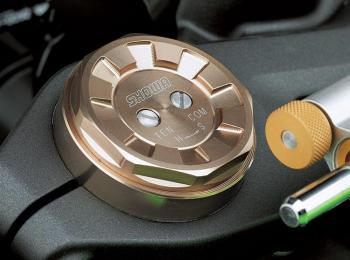
Expect to see more BPF forks, with their characteristic compression and rebound (also known as tension - see the image above right and in the gallery) adjusted from the top of the forks.

article by Kevin Ash taken from http://www.ashonbikes.com/node/389

24 February, 2009

24V Starter Setup

Just gotten my 24V starter setup done yesterday. This following was a setup suggested by APE. It was however not adopted as the 2nd battery does not get charged.
And the following was what was being sold for USD$159!! No way i'm paying so much for some wires and a switch.
So I went out shopping for the parts and with a circuit diagram in hand. Went to this shop in Sim Lim Tower and asked the shop owner for recommendation for wires to use. And to my surprise, he recommended a wire only 10% the thickness of a 8AWG wire. I emphasized that it'll be used to carry up to 30A of current and he stands by his suggestion with good faith. He states that the wire is US Military Grade approved and went ahead to demonstrate the effectiveness of the shielding by burning it with a blow torch. Still, at the back of my head, there's a doubt that such a thin wire can carry such high current. Simply because high school physics teaches us that, R=p(L/A). The cross sectional area of this is significantly smaller than the 8AWG so surely the resistance of the wire must be quite high.

Backed by the confidence of the shop owner, I bought about 10m of the wire and headed back to start on the installation yesterday. Clifford took over the tedious work of crimping and soldering the wires while I just check the connections.

Moment of truth came when we just fixed up the 24V section of the circuit and decided to test the stability of the wires I've bought. As I turned the ignition on, pulled in the clutch, made sure that the switch is switched on, gingerly I pressed on the starter button. "Click," the starter relay went, I pressed a few more times, "click, click, click" was the reply from the starter relay and nothing else happened.

"Crap!" I thought to myself. As Clifford told me to double check the circuit diagram, I was quite certain the switching circuit was correct. It's the 24V connection part that I'm not too certain. So immediately, I went online and checked the wiring sequence. Turns out, indeed the wires are installed in the wrong order. And so, a simple swap was done and the next trial was up.

Once more, I turned on the ignition, pulled the clutch in and pressed on the starter switch. "Wheezzz" and the bike sprang to life. Never have I heard the starter turn with such ease and speed before. The sound was almost as exciting as it gets. Immediately I killed the engine and started it up again to hear the start again. "Wheezzz," effortlessly, the starter just jumped the engine to life.

This time round, we left the bike running till the fan came on. Just so that we can test the hot start capability of the 24V setup on a high compression engine. As the fan came on, I killed the engine and proceeded to crank it up again. And just like clockwork, the starter spun up with ease and the engine sprang back to life. Ok! Mission accomplished! Sort of...

The rest of the installation is just to wire up the parallel 12V part of the circuit and install back the bodywork. With that, I can safely say good bye to hot start nightmares!

Blog Widget by LinkWithin